Crossover Network Design
I took EE 230 in the spring semester of 2020, the semester when the pandemic started. Before the pandemic, EE 230 was one of the best classes I have ever taken, largely because of this project.
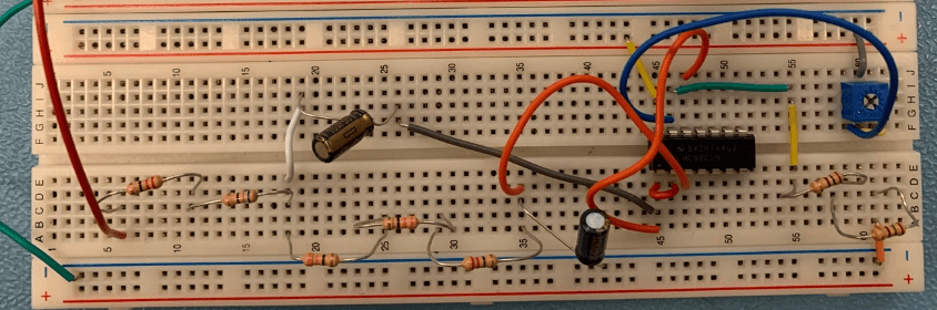
After learning about the Laplace Transform, how to represent circuit elements as impedance values, and filter design, we got to pick a project that involved all three to demonstrate our knowledge. We chose to build a crossover network, the purpose of which is to separate low frequency signals from middling frequency signals from high frequency signals. My role in this project was to design the low pass filter, and to do so I used the textbook and Dr. Tuttle’s notes. The framework I used to base my design off is called a Sallen-Key Lowpass filter.
As I was just learning circuit design, everything in this project was done using a breadboard and through hole components. My final design can be seen below, with more details included in the lab report.
Skills learned in this project:
- Filter Design
- Prototyping and Testing using a breadboard
- How to use non-ideal amplifiers
Automated Test PCBs
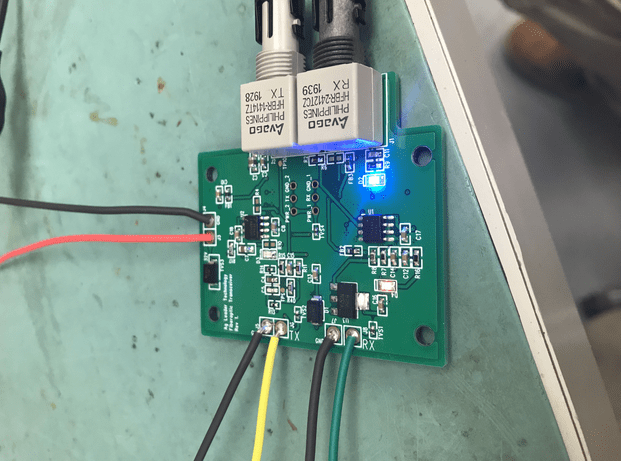
When I was an intern for Ag Leader Technology, I designed a circuit board to aid in EM testing some of our products for FCC and UL certification. The board would take data from a USB port, turn it into optical data, and send it into a Faraday Cage to be transformed back into USB data and received by a computer inside. We did this so that there would be no EM radiation generated by pushing a USB signal to the device we were testing.
A lot of this project was learning how to read through data sheets and find parts that would do what I needed. After doing that, I would design those parts in PADS (a circuit design software that allows you to make schematics and lay out boards) and find a way to supply them with what they needed to operate. The resources I used largely came from the Ag Leader staff and their experience.
There are a lot of factors to consider when designing circuit boards, more than I had initially thought. In my first revision of the board, I had included a capacitor which was unable to operate at the frequency that I needed it too. Luckily, and this is another important thing that the staff at Ag Leader taught me, I had included lots of Do Not Populate (DNP) pads (places to solder parts) in which I could add the proper capacitors to fix the problem.
Skills learned in this project:
- PADS Schematic and Layout
- Circuit design best practices
- Basics of validation testing
Due to the nature of this project, there are no supporting documents that I have access too, nor would they be helpful in understanding the project.
EE 414 Final Project
This semester, I took a class called Microwave Electronics in which we learned how to design high frequency amplifiers, oscillators, and filters. Throughout the lab portion of the class, we designed and tested all three of these circuits so that, for the final project, we would be able to place them all on a board, fabricate the board, and study how our work would perform in a physical implementation. To accomplish this, we used Dr. Neihart’s notes, our textbook, and help of our gracious TA.
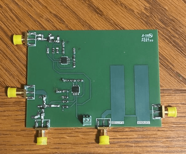
Above is the board that we designed. Unfortunately, only our filter ended up working, but it was still a great experience, and demonstrated how important it is to design carefully when working with high frequencies. We believe that part of the reason that the amplifier failed is that, while designing it in ADS (high frequency circuit design software) it did not need a stability network, but in it’s physical implementation, unaccounted for variables may have destabilized the transistor in a way we did not expect.
Working on this project gave me the opportunity to learn about the differences that arise when you switch from working on DC circuits to high frequency circuits. Additionally, it gave me the opportunity to learn a new circuit design software, ADS. The tools that ADS provides for analyzing circuit performance are incredible, and I have never worked so closely with simulation before.
Skills learned in this project:
- High Frequency RF Design
- ADS Circuit Analysis Software
Attached are our lab reports detailing all of the designs that went onto our final project board. I hope you enjoy! Side note – I would like to point out how much better these lab reports are than the lab report I did for EE 230. I am pleased with how I have improved.
